HEPA & ULPA
filter selection guide.
A practical guide to filter construction, media, efficiency, airflow, sealing and installed performance.
Selecting a replacement involves more than matching its outside dimensions. The filter, its housing and the operating conditions must work together. Use the following information to prepare a specification and compare documented product configurations.
Explore HEPA & high-efficiency filters ↗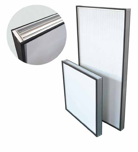
Choose the format for its filtration stage.
Deep-pleat / separator HEPA
A deep-pleat filter contains a folded media pack held within a rigid frame. Separator constructions maintain spacing between the folds. These filters are used in compatible air-handling units and high-efficiency housings.
Check the filter depth, rated airflow, initial resistance and mounting arrangement. A standard-capacity filter may suit an installation with sufficient space and a moderate airflow requirement.
High-capacity and V-bank designs
Higher-capacity constructions accommodate different airflow requirements within a defined footprint. A V-bank arrangement positions media packs at an angle inside the frame. Selection depends on the available space, tested airflow capacity and pressure drop.
V-bank describes a construction, not an efficiency rating. HVAC V-bank filters and HEPA V-bank filters are not automatically interchangeable.
Mini-pleat HEPA / ULPA
A mini-pleat pack uses closely spaced folds within a compact assembly. Suitable configurations provide final filtration in cleanroom ceilings, terminal housings and filter modules.
Match the efficiency class, pack depth, usable filter face area and seal to the equipment. A filter that physically fits may still have the wrong airflow resistance or installation geometry.
Upstream filtration
Filters ahead of the terminal stage reduce the particle load reaching the final filters. A suitable upstream arrangement can help protect the more demanding final filtration stage.
Specify each stage separately. An upstream filter is not a substitute for the required terminal HEPA or ULPA filter.
Specify the tested rating.
HEPA and ULPA identify high-efficiency particulate filtration categories. The required class must come from the application specification. Record the complete rating and test method, rather than relying on a product name, a color or a percentage without its test conditions.
Ask for the efficiency documentation for the exact filter assembly and its specified airflow. Do not assume that two filters with similar dimensions, media descriptions or appearance have equivalent performance. A filter rating also does not, by itself, establish a cleanroom’s classification.
Keep performance documents tied to the supplied model and configuration. Confirm whether the application requires individual filter test records and installed integrity testing.
Match the media to the process and test method.
Microglass media
Fine glass-fiber media is used in many HEPA and ULPA constructions. Evaluate the documented efficiency, airflow resistance and handling requirements of the supplied assembly.
Where the process has additional material restrictions, such as low-boron requirements in some microelectronics applications, include those requirements in the specification.
Membrane media
Membrane constructions are another media option in the wider HEPA/ULPA market. Their resistance, durability and suitability depend on the particular design. Single-layer and multilayer constructions should not be treated as interchangeable.
Compatibility with an oil-based test aerosol is especially important. Select a membrane construction explicitly approved for the intended test method; confirm product availability before specifying it.
PAO and PSL compatibility
PAO and PSL are different challenge aerosols used in filter testing. Approval for one does not establish approval for the other. Provide the intended aerosol and test procedure when requesting a filter, and obtain written compatibility information for the actual media and assembly.
Confirm cleaning-agent compatibility separately. Do not infer chemical resistance from the efficiency class or media family.
Compare filters at the same operating point.
Airflow is a volume of air per unit of time, commonly stated in CFM or m³/h. Face velocity describes the speed of air through a defined face area. Filter media area, outside dimensions and the unobstructed face opening are different measurements.
A larger frame does not necessarily provide proportionally more usable face area. Retaining hardware and the housing opening can restrict that area. Room-side and top-side replacement arrangements may therefore have different airflow characteristics, even when the filter efficiency class is the same.
Airflow calculation example
Airflow (CFM) = face velocity (ft/min) × open face area (ft²). An open area of 4 ft² at 250 ft/min corresponds to 1,000 CFM. This is a calculation example, not a FIRSTAIR product rating; use the actual open area and the manufacturer’s tested performance.
Compare initial pressure drop at the required airflow, in the same units and for the same configuration. Include the housing and other system components when checking the fan’s available pressure. Lower resistance can reduce the energy needed to move the same air, but actual savings depend on the fan, controls and operating hours.
Evaluate purchase cost together with documented resistance, service access and replacement requirements. Do not assume a fixed energy-saving percentage or service life for an entire media family.
The sealing arrangement must match the housing.
Gasket configurations
Record the gasket location, dimensions and required compression arrangement. The frame must seat correctly against the housing’s sealing surface, with the specified retaining hardware.
Knife-edge and gel-seal configurations
These systems depend on a compatible edge and sealing channel. Identify whether the filter or the housing carries each feature. Verify the geometry and installation instructions before selecting a replacement.
Include the frame material, actual dimensions, seal position and a photograph or drawing with the inquiry. Matching the nominal size alone does not confirm a compatible seal.
Efficiency testing and leak testing answer different questions.
Efficiency documentation describes filtration performance under stated test conditions. Installed integrity testing evaluates the completed installation for leakage. Media damage, frame damage or an unsuitable seal can compromise an otherwise correctly rated filter.
Testing may introduce a challenge aerosol upstream through the ductwork or through a suitable local injection port. The qualified testing team must determine the procedure, aerosol distribution and sampling arrangement for the equipment.
Confirm the applicable acceptance criteria and testing schedule for the facility. Do not apply one leak limit or frequency to every cleanroom. Keep the filter identification, installation details and test results together in the maintenance record.
Plan for installation and service access.
Confirm whether the filter is replaced from the room side or from above the ceiling, and whether it is a separate replaceable filter or part of a disposable terminal assembly. Access affects the replacement procedure and may also affect the usable face area.
Inspect the filter, frame and seal before installation. Follow the supplied handling instructions, protect the media from contact and damage, and use the specified mounting method. Arrange the required post-installation checks before returning the system to service.
Use the equipment’s operating requirements and maintenance procedure to determine replacement timing. Record changes in airflow, resistance and integrity-test results; a calendar interval alone does not establish that every filter is still suitable.
Give us the complete filter requirement.
Start with the existing filter label and the equipment specification. Clear photographs of the full filter, frame profile and seal are useful when identifying a replacement.
FIRSTAIR product specifications and available options must be confirmed for the selected model. General selection guidance does not replace the approved product documentation or the facility’s qualification requirements.
Include with your inquiry
- Existing filter manufacturer, model and label photo
- Required efficiency class and test method
- Actual width, height and depth, including units
- Design airflow and allowable pressure drop
- Media and process-specific material requirements
- Frame material, seal type, seal location and housing details
- Room-side or top-side replacement access
- Test aerosol and required filter documentation
- Application, quantity and delivery requirements
Related filter families.
Review the construction and documented configurations for your application.
Mini-Pleat HEPA Filters
Final filtration for applications requiring a specified high-efficiency filter assembly and an appropriate sealing arrangement.
View product details ↗Separator HEPA Box Filters
A deep pleated pack with separators for final filtration in compatible high-efficiency housings.
View product details ↗U15 Knife-Edge Mini-Pleat Filters
A documented U15 configuration for critical-air installations requiring this class and a compatible knife-edge housing.
View product details ↗Gel-Seal HEPA Filters
A gel-channel sealing arrangement for terminal housings designed to accept this filter geometry.
View product details ↗